Matthew Chin, CC BY-NC-ND
Jean Paul Santos, University of California, Los Angeles; Joshua M Kovitz, University of California, Los Angeles, and Yahya Rahmat-Samii, University of California, Los Angeles
When people think about antennas, they often picture old television sets with “rabbit ears” – two metal rods poking above the screen. Essentially, antennas are devices that allow the wireless transfer or reception of radio signals. They come in various sizes and shapes. For instance, it’s your cellphone’s antenna that allows you to stream videos, post a social media status, use GPS to find a restaurant and call a friend.

NASA/JPL-Caltech, CC BY
This wireless technology opened the door to space exploration. Neil Armstrong’s voyage to the moon was possible because antennas allow communication between engineered space vehicles and Earth. It’s an antenna that allows the Mars rovers to communicate with Earth from millions of miles away. To gather valuable scientific data, rovers often take measurements, pictures and video, then send them back home via radio waves at high frequencies, through their antennas.
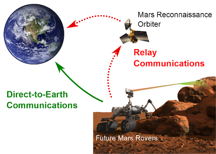
Currently, the Mars rovers primarily rely on what’s called indirect or relay communications. They send their data to a much larger satellite antenna, called the Mars Reconnaissance Orbiter, which then sends it all on to Earth at high transmission rates. The frequencies of transmission are in X-band, near 8 GHz, which has a radio wavelength close to 1.5 inches.
Joshua Kovitz, Jean Paul Santos and Yahya Rahmat-Samii, CC BY-NC-ND
Our group here at the UCLA Antenna Research, Analysis, and Measurement Laboratory specializes in designing advanced antenna systems, including spacecraft antennas for future space missions. Now, with help from engineers at NASA’s Jet Propulsion Laboratory (JPL), we’re working to create a small yet powerful antenna that could allow the Mars rover to communicate directly with Earth, potentially cutting out the middleman.
Read Also: Two Satellites Just Avoided a Head-on Smash
At the present time, the Mars rover can relay information to the Mars Reconnaissance Orbiter for just 15 minutes twice a day due to orbit conditions. Allowing the Mars rover to connect directly with Earth could offer a big increase in communication time – much more data could be sent back and forth when the rover is in direct line-of-sight. A direct link would also be an advantage in the event that large satellite orbiters are no longer available.
The challenge is to create an upgraded link that can do the job but also fit on the next upcoming Mars rover mission, Mars2020.
Good signal strength over astronomical distances

Joshua Kovitz, Jean Paul Santos and Yahya Rahmat-Samii, CC BY-NC-ND
We need to achieve good signal strength in the small space set aside on the rover for an antenna. The physics of radio waves tells us that the larger the antenna, the more power it can receive. Think of an antenna as like a bucket collecting rain. The larger the bucket’s opening, the more water it can catch at any given time. As long as the antenna is much bigger than the wavelength, it works the same way: the bigger it is, the more power it can receive or transmit. With more power, the data can be better extracted from the radio waves that carry pictures, video and commands. Extracting the data works similarly to modern television signals, with audio and video carried by radio waves.
For future Mars rovers, 40 cm x 40 cm x 5 cm is potentially the maximum volume that the antenna can occupy. With the available area set, our job as antenna engineers is to figure out the best and most efficient way to use all the space given to maximize the amount of power.
Other criteria for the antenna to work on a Mars 2020 rover include:
- must be lightweight
- must run on the prospective power available for radio transmissions – about 100 Watts, the same amount used by a bright incandescent lightbulb
NASA/JPL-Caltech, CC BY
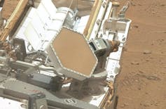
- must be aligned with the Earth’s antenna. A robotic supporting arm called a gimbal can mechanically position the antenna. The Curiosity mission used a similar gimbal to steer its high-gain antenna.
Adding up antenna elements into one array
The big idea is to combine many small antennas (often called antenna elements) to make an altogether larger antenna. You can think of this antenna concept as like an organ system. An individual organ, such as the heart, can operate in and of itself. It’s when it’s combined with other organs that it can maintain a human being.
Joshua Kovitz, Jean Paul Santos and Yahya Rahmat-Samii, CC BY-NC-ND
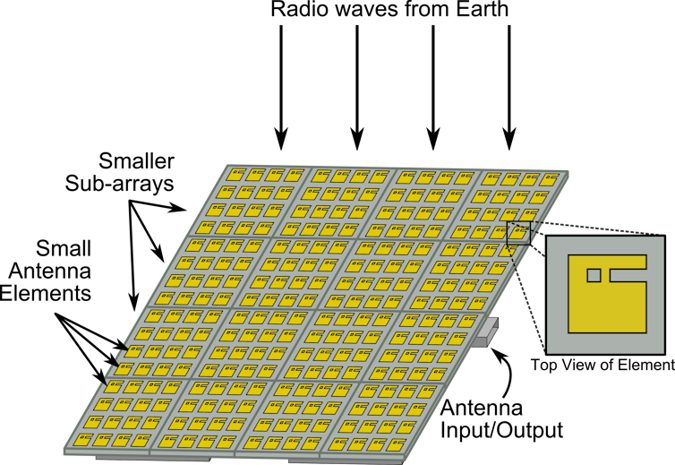
Our antenna “organs” begin with a specialized geometry that looks like half of the letter “E.” We derived it from the original E-shaped antenna design we’ve already had a lot of success with. This novel “half-E” shape allows the antenna to transmit and receive radio signals which are circularly polarized. Basically that means the polarization of the radio waves can be oriented in a special configuration that helps reduce the effects of atmospheric gases and particles on the waves as they travel. It can also help to make sure a strong signal is maintained even if the rover itself or the antennas are moving.
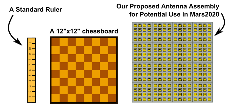
When enough of these antenna elements – 256 in this case – are combined together just right into what antenna engineers call an array, the whole can transmit and receive much greater power.
Joshua Kovitz, Jean Paul Santos and Yahya Rahmat-Samii, CC BY-NC-ND
The overall complete array should fit nicely within the required volume, whose maximum area is comparable to a standard 12-inch by 12-inch chessboard. It’s a compact way to pack the same antenna power into a much smaller space than if we relied on larger, bulkier dish antennas that have the added disadvantage of being harder to stow on the rover during flight.
Jean Paul Santos, CC BY-NC-ND
Transforming a novel idea into a real prototype
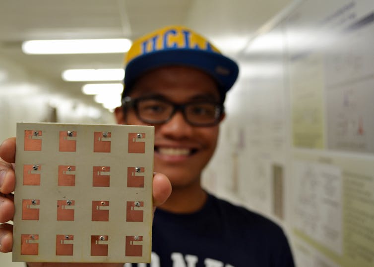
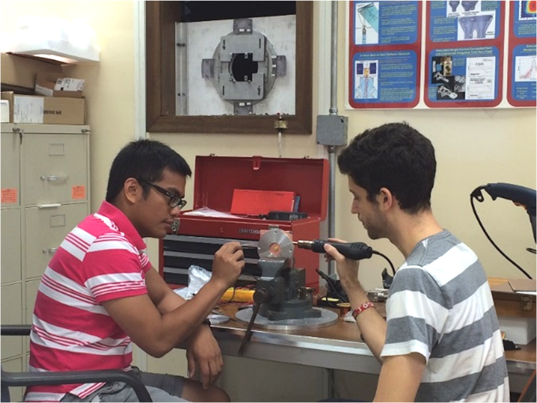
Of course, any exciting venture in engineering research worth its salt comes with an experimental demonstration. As a first step, we designed, built and tested one of the smaller 4-by-4 element sub-arrays. We used simulation software to first understand how the antenna would perform in real-life scenarios. We drew the antenna in a computer-aided drafting program, which included all the necessary materials such as metals, ceramics and wires.
Joshua Kovitz, CC BY-NC-ND
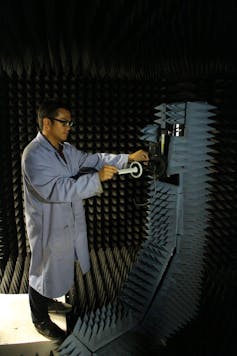
After much fine-tuning and verifying that the antenna meets the JPL requirements mentioned above, we began physically constructing it. And it took us several attempts. We started by taking a couple of pieces of lightweight ceramic coated with metal and used photolithography and chemical etching to create the specialized antenna geometry. Since this antenna is several layers, we had to solder them all together. When we tested the antenna’s actual performance, we were gratified to see our prototype behaved the way our simulations predicted!
With a successful prototyping of the 4-by-4 element sub-array, the next step would be to prototype the full-scale 16-by-16 element antenna. Ultimately, we’d like to test it on the Mars rover system itself at a NASA test site here on Earth. We hope that with this design, JPL can potentially augment its communication system so the rover can successfully call home directly.![]()
Jean Paul Santos, PhD Student in Electrical Engineering, University of California, Los Angeles; Joshua M Kovitz, PhD student in Electrical Engineering, University of California, Los Angeles, and Yahya Rahmat-Samii, Professor of Electrical Engineering/Electromagnetics, University of California, Los Angeles
This article is republished from The Conversation under a Creative Commons license. Read the original article.